How Accurate Solar CAD Designs Reduce Permit Revisions in the USA & Canada.
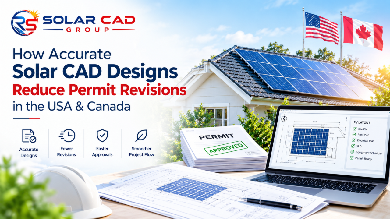
For solar installers, EPCs, contractors, and engineering teams, the permitting stage is one of the most important steps in bringing a solar project from design to installation. A project may have an excellent sales proposal, high-quality equipment, and a ready installation team, but the project can still face delays if the permit drawings are inaccurate, incomplete, or inconsistent.
One of the most common causes of these delays is the need for permit revisions.
Permit revisions can result from incorrect roof dimensions, improper module placement, missing setbacks, inconsistent electrical information, incomplete documentation, or failure to address local Authority Having Jurisdiction (AHJ) requirements.
While some revisions are unavoidable because of project-specific conditions or AHJ comments, many common corrections can be prevented before submission by using an accurate and well-coordinated solar CAD design workflow.
For companies managing multiple solar projects across the USA and Canada, accurate CAD design is not simply a drafting requirement. It can become an important part of improving project efficiency, reducing unnecessary back-and-forth, and keeping installations moving toward approval.
In this article, we will explore how accurate solar CAD designs can help reduce permit revisions, what common design mistakes lead to corrections, and why a professional solar design workflow is valuable for North American solar projects.
What Are Solar Permit Revisions?
A solar permit revision occurs when an AHJ, utility, engineer, or other reviewing authority requests changes or additional information before a solar project can move forward.
For example, an AHJ may review a submitted solar permit package and identify an issue with:
- Roof dimensions
- Module placement
- Fire access pathways
- Setbacks
- Electrical calculations
- Equipment locations
- Single-line diagrams
- Structural information
- Labeling
- System specifications
- Site plans
- Interconnection details
The design team then needs to make the requested corrections and resubmit the drawings.
One revision may appear minor, but repeated revisions can create significant delays when a company is managing dozens or hundreds of projects.
This is why it is better to identify potential issues before the permit package reaches the AHJ.
Why Permit Revisions Can Delay Solar Projects
Solar projects involve multiple teams and multiple stages.
A typical workflow may look like:
Sales → Site Survey → Solar Design → Engineering → Permitting → AHJ Review → Approval → Installation
If the permit package is returned for corrections, the workflow can move backward.
For example:
AHJ Review → Revision Request → Designer → Correction → Internal Review → Resubmission → AHJ Review
Every additional cycle can consume time.
For installers working with a large project pipeline, this can create a backlog of projects waiting for approval.
Permit delays can also affect:
- Installation scheduling
- Customer expectations
- Engineering workload
- Project timelines
- Internal coordination
- Revenue forecasting
- Crew planning
This is why reducing avoidable revisions is important for operational efficiency.
1. Accurate Roof Dimensions Create a Stronger Foundation
The roof plan is one of the foundations of a residential solar permit drawing.
If the roof dimensions are incorrect, the problem can affect multiple parts of the design.
For example, incorrect dimensions can influence:
- Module placement
- Setbacks
- Walkways
- Roof access
- Array size
- Equipment placement
- Structural calculations
- Fire access requirements
A professional CAD workflow should begin with reliable project information.
The roof should be represented accurately, including relevant roof planes, edges, ridges, valleys, obstructions, and other features that can affect the solar installation.
Accurate measurements allow designers to develop a PV layout that better reflects the actual installation conditions.
2. Precise Module Placement Helps Prevent Layout Corrections
A solar panel layout is not simply about fitting as many modules as possible onto a roof.
The design needs to consider the available roof area and applicable requirements.
Depending on the project, designers may need to consider:
- Roof edges
- Fire access
- Required pathways
- Roof obstructions
- Skylights
- Vents
- HVAC equipment
- Module orientation
- Equipment clearances
- Structural considerations
An inaccurate module layout can lead to an AHJ requesting changes after submission.
By checking these factors during the design stage, potential problems can be identified before the permit package is submitted.
3. Accurate Setbacks and Clearances Matter
Setbacks and clearances are another common area where permit drawings may receive comments.
A solar array may need to maintain appropriate clearance from certain roof features or access areas based on the applicable requirements for that project.
If the drawings do not clearly demonstrate the required clearances, the reviewer may request additional information or changes.
A detailed CAD design can visually communicate:
- Module-to-edge distances
- Access pathways
- Equipment clearances
- Roof access areas
- Obstruction clearances
This makes the drawing easier to review and helps the design team identify potential conflicts before submission.
4. Consistency Between Drawings Is Critical
A solar permit package usually contains more than one drawing.
Different sheets may describe the same project from different perspectives.
For example:
Roof Plan Shows the physical location of the PV modules.
Electrical Plan Shows electrical equipment and wiring information.
Single-Line Diagram Shows how the system components are electrically connected.
Equipment Schedule Provides information about modules, inverters, batteries, and other equipment.
All of these documents should tell the same story.
If the roof plan shows 30 modules but the electrical documentation indicates a different module count, the reviewer may request a correction.
Similarly, the inverter model, system capacity, battery information, disconnect locations, and other project details should remain consistent across the package.
5. Accurate Single-Line Diagrams Reduce Electrical Revisions
The Single-Line Diagram, commonly referred to as an SLD, is an important part of many solar permit packages.
It provides a simplified representation of the electrical system.
Depending on the project, an SLD may include:
- PV modules
- Inverters
- Combiner equipment
- Disconnects
- Main service panel
- Electrical service
- Energy storage systems
- Conductors
- Overcurrent protection
- Grounding and bonding
- Interconnection information
The SLD should accurately represent the proposed system.
If the SLD does not match the equipment or configuration shown elsewhere in the permit package, the AHJ may request revisions.
A coordinated CAD and electrical design process helps reduce these inconsistencies.
6. Equipment Information Should Match the Actual Design
Another common source of permit comments is inconsistent equipment information.
A solar project may include:
- PV modules
- Inverters
- Optimizers
- Batteries
- Disconnects
- Rapid shutdown equipment
- Main service equipment
- Load centers
- EV chargers
The model numbers and system information shown in the drawings should correspond to the actual proposed equipment.
For example, if the permit package identifies one inverter model while another drawing shows a different model, the reviewer may ask the design team to clarify or correct the information.
Accurate equipment documentation helps create a more reliable permit package.
7. Local AHJ Requirements Should Be Considered Early
One of the biggest challenges of solar permitting in North America is that requirements can vary between jurisdictions.
A solar installer may work on projects in multiple cities, counties, states, or provinces.
Each jurisdiction may have its own requirements regarding:
- Required drawing sheets
- Site plans
- Fire access
- Roof layouts
- Structural documentation
- Electrical details
- Equipment labeling
- Setbacks
- Interconnection
- Application documentation
A design approach that works for one location may not automatically be suitable for another.
This is why solar design teams should identify the applicable requirements before finalizing the permit package.
Solar CAD Design for Projects Across the USA
The USA has a large and diverse solar market, with permitting requirements that can vary considerably between jurisdictions.
A solar project may need to comply with applicable:
- Electrical requirements
- Building requirements
- Fire requirements
- Utility requirements
- Local AHJ requirements
- Interconnection requirements
Because local requirements can vary, solar installers need permit drawings that are prepared with the specific project location in mind.
Accurate CAD documentation can help designers clearly communicate the proposed installation and provide the information required for review.
Solar CAD Design for Projects Across Canada
Canada also has a growing solar market, but requirements can vary depending on the province, municipality, utility, and project type.
Solar projects may need to address applicable:
- Provincial requirements
- Municipal requirements
- Electrical requirements
- Building requirements
- Utility requirements
- Interconnection requirements
For companies working across multiple Canadian locations, a consistent but flexible CAD workflow can help maintain design quality while adapting documentation to project-specific requirements.
8. Accurate Structural Information Supports Permit Review
Structural information can also be important for solar permitting.
The design may need to communicate information related to:
- Roof construction
- Mounting locations
- Attachment points
- Structural members
- Equipment loads
- Mounting systems
The exact documentation required depends on the project and jurisdiction.
When structural information is incomplete or inconsistent, additional review comments may occur.
Coordinating structural information with the overall solar CAD package can help create a more complete project submission.
9. Clear Drawings Make AHJ Review Easier
The purpose of a permit drawing is not only to document the project for the design team.
It also needs to communicate the proposed installation clearly to the reviewer.
A professional drawing should be:
- Organized
- Legible
- Consistent
- Properly labeled
- Dimensioned where required
- Easy to interpret
When information is difficult to locate or drawings contain unnecessary inconsistencies, the review process can become more complicated.
Clear CAD documentation allows reviewers to understand the proposed system more efficiently.
10. Accurate CAD Design Reduces Back-and-Forth
Consider a typical revision cycle.
An AHJ identifies three issues:
- Incorrect module setback
- Missing equipment information
- SLD does not match the PV layout
The designer must then:
- Review the comments
- Locate the affected drawings
- Correct the layout
- Update the electrical documentation
- Update the SLD
- Recheck the package
- Prepare revised files
- Resubmit the permit
If the original design had been properly coordinated, these issues might have been identified before submission.
This is where quality control becomes important.
The Importance of Solar Design Quality Control
Before submitting a permit package, a design team should perform an internal review.
A quality-control checklist can include:
Site Plan
- Project address verified
- Building location accurate
- Required site information included
Roof Plan
- Roof dimensions checked
- Roof planes represented correctly
- Obstructions identified
- Module count verified
- Setbacks checked
Electrical Plan
- Equipment locations verified
- Conductor information checked
- Electrical equipment coordinated
SLD
- Module count matches
- Inverter information matches
- Battery information matches where applicable
- Disconnects are represented correctly
- Electrical configuration is consistent
Equipment Schedule
- Equipment models verified
- Quantities verified
- System information consistent
Final Review
- Drawing titles checked
- Project address checked
- Revision information checked
- All required sheets included
- AHJ-specific requirements reviewed
This type of internal review can catch errors before they reach the permitting authority.
Common Solar CAD Mistakes That Can Lead to Revisions
Some mistakes appear small but can create unnecessary corrections.
Incorrect Project Information
A wrong address, project name, or customer information can create confusion and may require document corrections.
Incorrect Module Count
If the module count differs between drawings, the package may need revision.
Inconsistent Inverter Information
The inverter shown on the SLD should correspond with the equipment schedule and other documentation.
Missing Roof Obstructions
Ignoring vents, skylights, HVAC units, or other roof features can create layout problems.
Incorrect Setbacks
Insufficient or unclear clearances can result in reviewer comments.
Missing Electrical Details
Incomplete electrical information can make the package difficult to approve.
Poorly Coordinated Revisions
When one drawing is updated but related drawings are not, inconsistencies can appear.
How Accurate CAD Designs Save Time for Solar Installers
For a solar company, time is an important operational resource.
When designers spend less time correcting avoidable mistakes, they can focus on completing new projects.
Accurate CAD workflows can help reduce:
- Rework
- Revisions
- Repeated emails
- Internal coordination
- Resubmission work
- Permit-related delays
This can become particularly valuable for installers managing a high volume of projects.
How Accurate Designs Can Improve Customer Experience
Homeowners and commercial customers generally want their solar projects to move forward without unnecessary delays.
When a project is delayed because of repeated permit revisions, customers may have questions about the timeline.
A smoother design and permitting workflow can help installers provide better project visibility.
Although accurate CAD design cannot guarantee a specific approval timeline, it can help reduce avoidable issues that may otherwise slow down the process.
Why Solar Companies Outsource CAD Design
Many solar installers have strong sales and installation teams but do not want to maintain a large internal CAD department.
Outsourcing solar CAD services can provide access to specialized design support without requiring a company to build a large in-house team.
A solar CAD partner can support:
- High project volumes
- Residential projects
- Commercial projects
- Permit plan sets
- Design revisions
- Electrical drawings
- SLDs
- Structural documentation
- Interconnection drawings
- Engineering coordination
This allows installers and EPCs to focus more on sales, customers, installation, and project management.
How RS Solar CAD Group Supports Solar Projects
RS Solar CAD Group provides solar CAD and engineering support for solar installers, EPCs, contractors, and other solar professionals working across the USA and Canada.
Our services include:
- PV Layout Design
- Solar Permit Plan Sets
- Permit Revisions
- PE/EE Stamping
- SLD / NEC Drawings
- ESS & Interconnection Design
- Residential Solar Design
- Commercial Solar Design
Our focus is on creating accurate, coordinated, and professional solar documentation that can support the permitting and installation workflow.
Every project has its own requirements, so our design process is structured around the available project information and applicable requirements.
A Better Solar Design Workflow
A strong solar design workflow can be summarized as:
1. Review Project Information Understand the site, customer information, equipment, and project requirements.
2. Develop the PV Layout Create the roof and module layout based on accurate project information.
3. Coordinate Electrical Design Develop electrical documentation that corresponds with the proposed system.
4. Prepare the SLD Ensure the electrical configuration matches the rest of the permit package.
5. Review Local Requirements Consider the applicable AHJ and project-specific requirements.
6. Perform Quality Control Check dimensions, module counts, equipment, electrical information, and documentation.
7. Finalize the Permit Package Prepare the drawings for submission.
8. Handle Revisions if Required Address AHJ comments and update the affected drawings consistently.
This workflow helps create a more structured approach to solar permitting.
The Business Value of Reducing Permit Revisions
Reducing unnecessary revisions is not only a technical benefit. It can also provide operational benefits.
A more efficient design workflow can help solar companies:
Improve project turnaround
Less rework can allow design teams to process projects more efficiently.
Reduce administrative workload
Fewer avoidable corrections can reduce repeated coordination.
Manage higher project volumes
An organized CAD workflow can support companies handling multiple projects simultaneously.
Improve internal coordination
Consistent drawings make it easier for sales, engineering, permitting, and installation teams to work from the same project information.
Keep projects moving
Reducing preventable design issues can help minimize unnecessary interruptions during the permitting stage.
Conclusion
Solar permitting is an important part of the project lifecycle, and permit revisions can create unnecessary delays when drawings contain avoidable errors or inconsistencies.
Accurate solar CAD design can help address many of these challenges by creating clear, coordinated, and detailed documentation.
From roof measurements and PV layouts to setbacks, equipment locations, electrical drawings, SLDs, structural details, and AHJ-specific requirements, every part of the permit package contributes to the overall quality of the submission.
For solar installers, EPCs, and contractors working across the USA and Canada, a reliable CAD workflow can provide an important advantage.
The goal is not simply to produce drawings.
The goal is to create accurate, coordinated, and permit-ready solar documentation that supports the project from design through permitting and ultimately toward installation.
Better CAD accuracy can mean fewer avoidable revisions, less rework, smoother coordination, and a more efficient solar project workflow.
Frequently Asked Questions
1. What is a solar CAD design?
A solar CAD design is a technical drawing package used to represent the proposed solar installation. It can include PV layouts, roof plans, electrical drawings, equipment locations, SLDs, structural details, and other project documentation.
2. What causes solar permit revisions?
Common causes include inaccurate measurements, incorrect module placement, missing setbacks, inconsistent equipment information, incomplete electrical drawings, SLD inconsistencies, and missing jurisdiction-specific requirements.
3. Can accurate CAD designs guarantee permit approval?
No. Permit approval depends on the applicable AHJ, project conditions, codes, utility requirements, and other factors. However, accurate and complete drawings can help reduce avoidable errors and revision requests.
4. Why is the SLD important for solar permitting?
The SLD communicates the electrical configuration of the solar system. It should be consistent with the PV layout, equipment information, and other electrical documentation.
5. Why do solar companies need AHJ-specific drawings?
Different jurisdictions may have different requirements for permit documentation, setbacks, fire access, structural information, electrical details, and other project elements. Therefore, designs should be prepared according to the applicable project requirements.
6. How can installers reduce permit revisions?
Installers can reduce avoidable revisions by using accurate site information, following applicable requirements, coordinating all drawings, performing internal quality control, and working with experienced solar design professionals.
7. Can solar CAD services handle permit revisions?
Yes. Solar CAD teams can review AHJ comments, update the affected drawings, coordinate changes across the permit package, and prepare revised documents for resubmission.
8. What solar projects can CAD teams support?
Depending on their capabilities, solar CAD teams can support residential, commercial, rooftop, ground-mount, battery/ESS, and other solar projects.
About RS Solar CAD Group
RS Solar CAD Group supports solar installers, EPCs, contractors, and solar businesses across the USA and Canada with professional solar CAD and engineering services.
Our Services:
PV Layout Design | Permit Plan Sets & Revisions | PE/EE Stamps | SLD / NEC Drawings | ESS & Interconnection | Residential & Commercial Solar Design
Email: sales@rscadgroup.com Website: www.rssolarcadgroup.com